Custom Carbon Fiber Manufacturing · Engineering Guide
Yes—a STEP file can be an excellent starting point for manufacturing a custom carbon fiber component. But a valid 3D model is not the same as a production-ready composite design. Before tooling begins, the geometry, laminate, mold strategy, fitment, finish, and inspection requirements must be evaluated together.
Who this guide is for: automotive aftermarket brands, OEM/ODM sourcing teams, product designers, and buyers developing custom carbon fiber parts.
1. Can a carbon fiber manufacturer work from a STEP file?
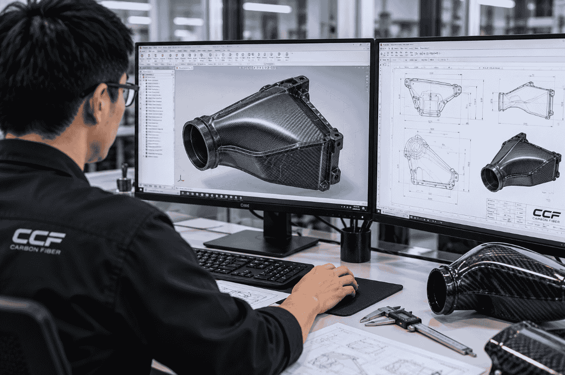
Often, yes. STEP (commonly supplied as .step or .stp) is a neutral CAD exchange format that allows a manufacturer to inspect and work with 3D part geometry across different CAD systems. It can help a supplier evaluate the shape, interfaces, and potential tooling approach for a custom part.
However, a STEP model alone usually does not define the full composite manufacturing specification. A supplier may still need information about fiber type, resin system, laminate thickness and orientation, surface finish, mounting points, structural loads, environmental exposure, and acceptable dimensional variation.
Practical takeaway: submit the STEP file for a preliminary design-for-manufacture (DFM) review, not as an assumption that tooling or production can begin immediately.
2. What is a STEP file—and what does it not tell the factory?
STEP is based on the ISO 10303 family of standards for exchanging product data. In typical automotive sourcing workflows, a STEP file communicates 3D geometry more reliably than a screenshot or a 2D image. The extension .stp is generally an alternative spelling of .step, not a different manufacturing method.
What a STEP model can help communicate
- Overall part geometry and spatial relationships
- Surfaces, edges, holes, flanges, and mounting features represented in the model
- Assembly geometry, if the exported file includes the relevant components
- A basis for tooling discussions and dimensional inspection planning
What still needs to be confirmed
- Material specification: cosmetic or structural carbon fiber, fiber architecture, resin, and any core material
- Laminate design: thickness targets, ply orientation, reinforcement zones, and local buildup
- Manufacturing route: prepreg, wet layup, infusion, compression molding, or another appropriate process
- Finish: visible weave, clear coat, gloss or matte appearance, and acceptable cosmetic defects
- Fitment: mating components, fasteners, inserts, gaskets, sealing interfaces, and clearance envelopes
- Validation: dimensional inspection, test-fit expectations, and performance tests when required
A file may also require geometry repair if it contains missing surfaces, gaps, overlapping faces, or problematic imported solids. Always specify the units and revision identifier alongside the export.
3. Seven checks before a STEP design becomes a carbon fiber part
3.1 Geometry and surface continuity
The manufacturer checks whether surfaces are complete and whether transitions, small radii, deep recesses, and sharp features are practical for the selected composite process. A visually smooth CAD model can still contain geometry that is difficult to lay up consistently.
3.2 Mold access, parting lines, and demolding
Unlike machining a metal part from solid stock, composite manufacturing frequently requires a mold and a feasible release direction. Undercuts, enclosed cavities, and complex return flanges may require split molds, removable cores, separate bonded components, or design changes. Parting-line placement can affect both appearance and cost.
3.3 Laminate thickness and fiber drapability
Carbon fiber fabric and prepreg do not behave like a uniform plastic shell. Fiber orientation, corner radii, ply drops, and material buildup influence whether a laminate can conform to the geometry without wrinkles, bridging, or excessive resin-rich areas. Thickness should be engineered for the application rather than inferred from the CAD surface alone.
3.4 Structural requirements and service environment
A decorative engine cover and a load-bearing bracket require different design evidence. Engineers may need to consider loads, vibration, heat, moisture, UV exposure, impact, and chemical contact. For an engine-bay component, the resin system and installation location matter; carbon fiber appearance alone does not establish thermal suitability.
3.5 Mounting, inserts, and interfaces
Fastener holes, bonded inserts, clips, brackets, and sealing surfaces must be designed with assembly loads and serviceability in mind. Some features may be trimmed or drilled after molding, while others require dedicated reinforcement or tooling provisions.
3.6 Surface quality and visible carbon weave
For cosmetic automotive parts, buyers should identify which surfaces are visible, which weave appearance is desired, and whether gloss, matte, or paint-ready finishing is expected. Complex curvature can change how the weave appears across a part; cosmetic requirements should be discussed before the mold design is finalized.
3.7 Inspection and acceptance criteria
Define critical dimensions, datum references, mounting-hole locations, edge-trim boundaries, and acceptable appearance before prototype approval. Without agreed acceptance criteria, both buyer and factory may interpret “good fitment” differently.
4. From STEP file to carbon fiber prototype: a practical workflow
- Initial inquiry and confidentiality: share a project overview, intended application, and appropriate confidentiality arrangements before transferring sensitive CAD data.
- CAD and requirement review: check file integrity, revision, units, mating parts, expected performance, and cosmetic requirements.
- Preliminary DFM feedback: identify undercuts, difficult layup regions, proposed part splits, tooling access, and information gaps.
- Scope and quotation: agree what is included in engineering review, tooling, sample production, finishing, inspection, and shipping. Separate one-time development charges from recurring unit prices.
- Design and tooling approval: freeze the relevant design revision and approve tooling assumptions before committing to manufacture.
- Prototype manufacturing: fabricate the tooling and sample using the agreed material and process, then trim and finish the component.
- Dimensional inspection and physical test fit: compare critical dimensions against drawings and verify the sample against the actual vehicle or mating assembly where possible.
- Revision and production readiness: document changes, approve the final sample, and agree inspection controls before repeat orders.
Important: these are recommended project gates, not a promise that every manufacturer offers in-house CAD redesign, simulation, physical vehicle testing, or certification. Confirm responsibilities in writing.
5. Why fitment is more than matching the STEP geometry
A nominally accurate model can still produce an assembly that is difficult to install. Composite parts can experience process-dependent variation, and additional variation can come from trimming, bonding, inserts, surface coating, and the mating vehicle components.
For a multi-piece carbon fiber airbox, for example, the lid, housing, ducts, mounting brackets, seals, and surrounding engine-bay components must be considered as one assembly. Manufacturing the lid first may be practical, but the interface geometry should be coordinated with the entire system before a mold is finalized.
How to reduce fitment risk
- Provide the full assembly model, not only isolated part files, when available.
- Identify datum surfaces and dimensions that control fitment.
- Share photos, measurements, or scans of the actual installation area where relevant.
- Specify required clearances, gasket compression, fastening method, and service access.
- Use a physical prototype and documented test-fit feedback before bulk production.
- Keep revision numbers consistent across parts, molds, and inspection records.
There is no universal tolerance number that can be promised for all carbon fiber parts. Achievable tolerances depend on size, geometry, tooling, manufacturing process, and measurement method. Ask the manufacturer to confirm critical tolerances for the specific design.
6. What affects the cost and lead time?
Two STEP files with similar overall dimensions can have very different development costs. Pricing depends on the manufacturing challenge, not simply the file format or the amount of carbon fiber visible in the finished part.
| Cost or schedule driver | Why it matters |
|---|---|
| Tooling complexity | Split molds, removable cores, and difficult release geometry increase engineering and fabrication work. |
| Part size and geometry | Large surfaces, deep features, and tight corners affect material use and labor. |
| Material and process | Fiber, resin, core, curing requirements, and process selection influence cost and repeatability. |
| Cosmetic requirements | Visible weave alignment, surface finishing, and rejection criteria may increase labor and inspection. |
| Fitment and validation | Fixtures, test-fitting, dimensional inspection, and revisions add project stages. |
| Order volume | One-time development charges are spread across different quantities; recurring unit cost also depends on process efficiency. |
For meaningful quotations, ask suppliers to distinguish one-time engineering/tooling charges, prototype/sample charges, and production unit pricing. Also clarify mold ownership, storage, revisions, payment milestones, and whether prototype tooling is suitable for production.
A reliable project schedule should distinguish CAD review, engineering changes, tooling, sample fabrication, inspection, buyer approval, and production. Avoid treating an estimated molding cycle as the complete project lead time.
7. RFQ checklist: what to send with your STEP file
A clear RFQ (request for quotation) helps a manufacturer evaluate the design and reduces repetitive questions. Include as much of the following as you can:
- 3D data: STEP/STP files with units, revision number, and assembly files where available
- Drawings: 2D dimensions, critical tolerances, datum references, and section views
- Vehicle application: make, model, year, variant, and relevant installation details
- Intended function: cosmetic cover, exterior aerodynamic part, duct, enclosure, or structural application
- Material and finish: target carbon fiber construction, appearance, coating, and temperature or environmental requirements
- Assembly details: mounting hardware, inserts, mating components, seals, and clearance limits
- Quantities: prototype count, initial order estimate, and potential annual demand if known
- Validation: test-fit responsibility, inspection requirements, and any required performance tests
- Commercial details: delivery country, target timeline, tooling ownership expectations, and applicable confidentiality requirements
If you do not have every item, identify what is missing rather than inventing specifications. A manufacturer can then explain which gaps prevent a firm quotation and which can be resolved during a paid development phase.
8. Common mistakes buyers should avoid
- Assuming the STEP file is the manufacturing specification: geometry does not replace laminate, finish, and inspection requirements.
- Approving a mold before assembly review: a single component may look correct while failing to fit the complete system.
- Comparing quotations without matching scope: one quote may exclude tooling, surface finishing, inserts, or sample revisions.
- Skipping prototype test fit: virtual fitment cannot always capture vehicle variation or real assembly conditions.
- Ignoring engineering ownership: decide who approves design changes, tests performance, and accepts final parts.
- Changing CAD revisions without tracking them: outdated files can lead to incorrect tooling or mismatched components.
Frequently Asked Questions
Can I send an STP file instead of a STEP file?
Yes. .stp and .step are commonly used extensions for the same STEP exchange format. The supplier still needs to check the exported model and confirm its units and revision.
Can a carbon fiber part be made without a STEP file?
Sometimes. A manufacturer may be able to begin an assessment from technical drawings, a physical sample, or scan data, but additional CAD development may be required before tooling. Confirm who performs and pays for that work.
Does a STEP file tell the manufacturer how many carbon fiber layers to use?
Not necessarily. A typical geometry export does not provide a validated laminate schedule. Ply count, orientation, resin, and reinforcement should be defined for the application and manufacturing process.
Can a STEP file be used directly for CNC machining a mold?
It can be an input to the tooling workflow, but mold design may require offsets, draft or release planning, parting surfaces, trim allowances, and process-specific features before CNC toolpaths are prepared.
Should I manufacture individual components before the full assembly is finalized?
Phased prototyping can reduce upfront commitment, but shared interfaces should be coordinated across the complete assembly first. Otherwise, later components may require costly redesign of parts or molds already produced.
Will a manufacturer guarantee fitment from my CAD file alone?
A responsible supplier should define what can be checked digitally and what requires physical test fitting. A fitment guarantee, if offered, needs explicit dimensional and acceptance criteria.
What should I ask before paying for tooling?
Ask about approved CAD revisions, tooling design, mold ownership, expected sample deliverables, revision charges, inspection standards, and what happens if the first sample fails the agreed acceptance criteria.
Conclusion: start with a manufacturability conversation
A STEP file is a strong starting point for custom carbon fiber manufacturing—but successful development depends on more than geometry. The best early conversations cover process selection, mold strategy, laminate requirements, fitment, validation, and the commercial scope of prototyping.
If you are sourcing custom automotive carbon fiber components, prepare your CAD data and project requirements before requesting a firm quotation. This gives your team and potential suppliers a clearer basis for discussing feasibility, risk, and next steps.
Discuss a Custom Carbon Fiber Project with CCF
Have a STEP/STP file, vehicle application, or custom component concept? Share your project requirements with CCF to discuss whether the design is a fit for our manufacturing scope and what information is needed for a quotation.
Explore CCF Wholesale & Custom Manufacturing
Manufacturing feasibility, engineering support, testing scope, costs, and lead times are subject to project review and written confirmation.