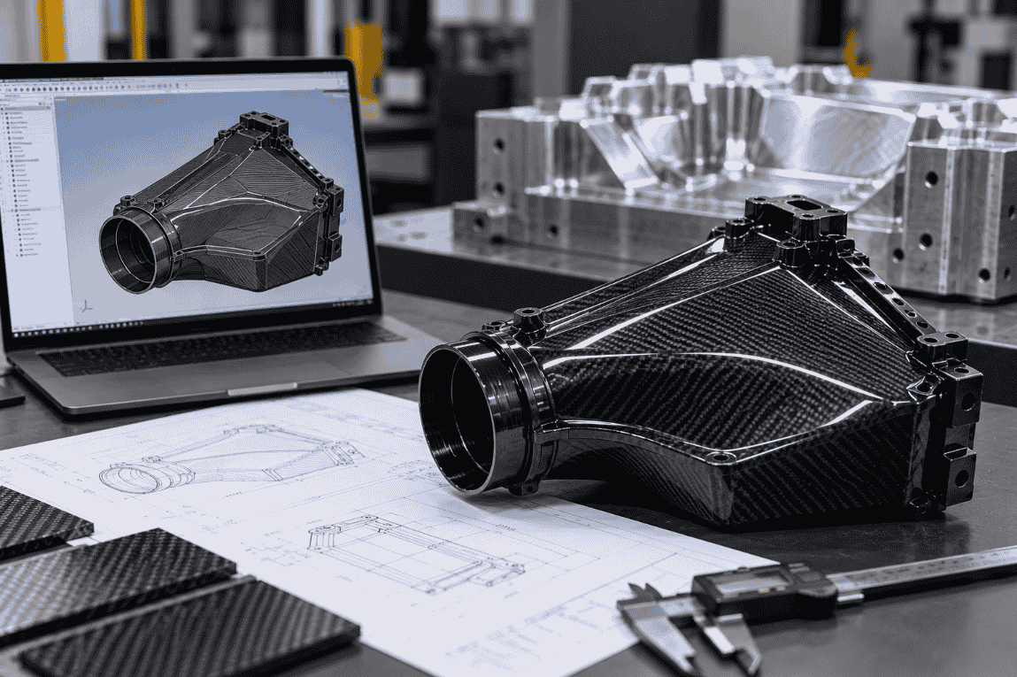
A polished 3D model is a useful starting point for a custom carbon fiber automotive component—but it is not yet a manufacturing-ready prototype. Between a CAD file and a physical part lie decisions about composite materials, mold geometry, laminate construction, dimensional control, and assembly validation. This guide explains the practical steps, deliverables, and decision points that OEM buyers and aftermarket brands should understand before committing to tooling.
Step 1: Review the CAD Model and STEP Files
Start by defining exactly what the file represents. A STEP or STP file typically exchanges 3D geometric data between CAD systems. It may describe the external shape accurately, but it does not necessarily communicate fiber orientation, laminate thickness, surface finish, allowable tolerances, or performance requirements. Those specifications should be supplied separately and reviewed together with the geometry.
Before a supplier assesses feasibility, verify the file revision, units, intended vehicle and model year, mating components, and whether the surfaces form a coherent solid or surface model. Include a 2D drawing when possible. Mark mounting interfaces, sealing faces, threaded inserts, and areas where the visible carbon weave matters.
Step 2: Adapt the Design for Composite Manufacturing
Geometry that is easy to machine from aluminum or print in plastic may be difficult to manufacture as a laminated composite. Deep recesses, tight internal corners, enclosed cavities, sharp transitions, and inaccessible undercuts can complicate layup, compaction, demolding, or trimming.
Critical design-for-manufacturing checks
- Tool access and release: Can the cured component be removed without damaging it? Is split tooling or a sacrificial core required?
- Corner radii: Are radii compatible with fabric drape and the selected process, rather than forcing bridging or wrinkles?
- Thickness transitions: Are local reinforcements and ply drop-offs designed to avoid abrupt stiffness changes?
- Interfaces: Are flange widths, bonding surfaces, fasteners, inserts, and seals accessible and adequately supported?
- Thermal environment: Are nearby engine heat sources, operating temperatures, and material limitations understood?
- Appearance: Does the design distinguish visible cosmetic surfaces from hidden structural surfaces?
For a carbon fiber airbox, for example, the inlet duct, housing, removable cover, filter access, sealing interface, and mounting brackets should be reviewed as an assembly. Optimizing each component independently can create misalignment when everything is installed together.
Step 3: Define Materials, Laminate Requirements, and Manufacturing Process
“Carbon fiber” is not a complete material specification. Performance depends on the fiber architecture, resin system, laminate schedule, cure cycle, quality controls, and operating environment. Cosmetic woven carbon, structural laminates, and hybrid constructions may require different approaches.
| Decision | Questions to resolve | Why it matters |
|---|---|---|
| Fiber architecture | Woven fabric, unidirectional plies, or a combination? | Controls appearance and directional stiffness. |
| Resin system | What heat, chemical, and environmental exposure is expected? | Influences durability and cure requirements. |
| Manufacturing route | Wet layup, vacuum infusion, prepreg, or another qualified process? | Changes tooling, labor, equipment, and repeatability. |
| Laminate schedule | Who defines ply count, orientation, and reinforcements? | Determines structural behavior and thickness. |
| Surface finish | Gloss, matte, clear-coated, painted, or unfinished? | Changes cosmetic acceptance criteria and finishing work. |
There is no universally best manufacturing process. A one-off appearance prototype, a functional engine-bay enclosure, and a repeatable production component may justify different process choices. Confirm the intended use and engineering responsibilities before selecting one.
Step 4: Develop the Tooling Strategy and Mold Design
Tooling converts the approved component geometry into a reproducible manufacturing surface. The mold design must account for release direction, flange geometry, access for material placement, expected processing temperature, dimensional stability, and any required parting lines.
Some parts can be formed with relatively simple open molds. Complex enclosed ducts may require multipart molds, cores, bonded subcomponents, or a revised geometry. The best option depends on shape, process, quantity, and required finish—not just the appearance of the CAD model.
What should be approved before tooling begins?
- Final part revision and critical interface dimensions.
- Tooling concept, split lines, and release strategy.
- Prototype quantity and whether tooling is reusable.
- Visible surface expectations and allowable witness lines.
- Who owns tooling, approves changes, and pays for revisions.
Tooling changes after machining or fabrication can be costly. A formal design freeze and documented approval point help reduce disputes about what was authorized.
Step 5: Prepare Materials, Lay Up the Laminate, and Cure
Once tooling and material specifications are approved, production moves to preparation. The mold is cleaned and treated with the appropriate release system. Fabric or prepreg is cut, oriented, and positioned according to the defined laminate plan. Inserts, local reinforcements, and bonding features are incorporated where specified.
Depending on the process, vacuum bagging, infusion, controlled heat, pressure, or combinations of these may be used to consolidate and cure the laminate. Actual parameters must follow the selected resin and process specification; there is no single cure schedule suitable for every carbon fiber part.
Step 6: Demold, Trim, Machine, and Finish the Prototype
After cure and any required cooling, the component is removed from the tool. The team inspects for visible defects such as wrinkles, resin-rich areas, void indications, edge damage, or cosmetic inconsistencies. Trimming and drilling bring the part to the specified boundary and interface geometry.
Machining composite material requires suitable tooling, dust control, and edge-quality checks. Holes and cutouts should be located from defined datums rather than estimated from the visible carbon weave. Bonding, insert installation, sealing surfaces, and coating are completed according to the agreed prototype scope.
Not every surface defect can be repaired without consequences. Establish acceptance criteria before finishing, especially for exposed-weave components where cosmetic appearance is a key purchase requirement.
Step 7: Inspect Dimensions, Interfaces, and Assembly Fitment
Dimensional inspection compares the prototype with the approved drawing or CAD definition. The inspection plan should prioritize functional features rather than treating every surface as equally critical. Depending on part complexity and requirements, inspection may involve calipers, gauges, fixtures, 3D scanning, or coordinate measurement.
Key checks for automotive carbon fiber components
- Mounting-hole location and fastener access.
- Flange flatness and gasket compression surfaces.
- Clearance to adjacent vehicle components.
- Alignment of lids, ducts, brackets, and connecting parts.
- Edge clearance, service access, and installation sequence.
- Cosmetic weave orientation and finish consistency.
One part passing inspection does not guarantee the complete assembly will fit. Tolerance stack-up, thermal expansion, gasket behavior, and mounting sequence can create problems only visible during assembly testing. Where possible, verify the prototype on the actual vehicle or a representative, controlled fixture.
For a deeper discussion of tolerance stack-up and fitment validation, see our custom carbon fiber parts fitment guide.
Step 8: Test the Prototype, Document Findings, and Revise
Prototype validation should be matched to intended use. A visual styling part may need installation and finish review; an engine-bay component may also require heat exposure, vibration, clearance, sealing, and other application-specific checks. Performance or safety claims should only be made after appropriate testing has been defined and completed by responsible parties.
Document the inspection findings, test conditions, fitment photographs, deviations, and proposed corrections. Assign a revision identifier to every change. If a lid needs a different flange or a mounting point moves, confirm the effects on mating parts and tooling before making the modification.
At the end of this stage, the project should have a clear decision: accept the prototype for its defined purpose, revise and retest it, or pause development because the design or manufacturing approach requires significant changes.
Step 9: Prepare for Repeatable Production
An approved sample is a milestone, not proof that future production units will be identical. Before scaling up, establish a controlled drawing revision, material specification, manufacturing instructions, inspection criteria, packaging requirements, and a change-management process.
Discuss how production quantities affect tooling life, cycle time, material procurement, cosmetic consistency, and rejection risk. Define whether the first approved sample becomes a reference sample and how subsequent parts will be compared against it.
| Project stage | Recommended deliverable | Buyer approval question |
|---|---|---|
| CAD review | Reviewed file revision and open-issue list | Are geometry and requirements complete? |
| DFM | Manufacturing feasibility feedback | Are design changes acceptable? |
| Tooling | Tool concept and agreed scope | Can tooling begin? |
| Prototype build | First physical sample and build record | Does the part meet initial expectations? |
| Validation | Inspection and test findings | Approve, revise, or retest? |
| Production planning | Released specification and quality plan | Is the process ready to scale? |
What Should Buyers Send When Requesting a Carbon Fiber Prototype Quote?
A complete RFQ helps a manufacturer identify technical uncertainties early and prepare a more useful response. Share as much of the following as is available:
- STEP/STP or other supported CAD files, plus revision history.
- 2D drawings showing dimensions, datums, tolerances, and mounting interfaces.
- Vehicle make, model, year, and installation photographs for automotive projects.
- Functional requirements, operating temperature, and environmental exposure.
- Target material, weave appearance, finish, and cosmetic acceptance expectations.
- Required prototype quantity, estimated future volume, and desired schedule.
- Existing mating parts or assembly files and any testing requirements.
- Responsibilities for engineering design, validation, tooling, and design changes.
If some information is unavailable, identify it explicitly instead of guessing. Early clarification is usually less expensive than discovering an incompatibility after tooling has been made.
Frequently Asked Questions
Can a manufacturer produce a carbon fiber prototype directly from a STEP file?
A STEP file can provide essential geometry, but it rarely defines all manufacturing requirements. The supplier must still assess tooling, material, laminate, tolerances, and intended use before confirming feasibility.
Do I need a complete engineering drawing as well as a 3D model?
A drawing is strongly recommended when dimensions, tolerances, materials, finishes, or inspection criteria are important. CAD geometry alone may not express these requirements unambiguously.
Can a carbon fiber prototype be made without a permanent production mold?
Some geometries and prototype goals allow alternative or temporary tooling. Suitability depends on the part, process, required surface quality, and number of samples.
How many prototype iterations are usually needed?
There is no reliable universal number. Iterations depend on design maturity, complexity, assembly interfaces, and test results. A clear review and approval process reduces avoidable revisions.
Is a cosmetic prototype suitable for functional engine-bay use?
Not necessarily. Functional applications may require appropriate resin selection, structural assessment, thermal and environmental validation, and other tests relevant to the part’s operating conditions.
Who is responsible for design and performance testing?
Responsibilities should be documented in the project agreement. Manufacturing a part to an agreed specification is different from taking responsibility for its engineering design or performance certification.
What is the best way to reduce prototype development risk?
Provide complete inputs, review the entire assembly, approve design-for-manufacturing changes before tooling, define inspection criteria, and use documented prototype validation before scaling production.
Discuss Your Custom Carbon Fiber Project with CCF
Developing an automotive carbon fiber component? Share your CAD or STEP files, application details, prototype quantity, and estimated production requirements with CCF to discuss manufacturing feasibility and next steps. Any engineering, testing, and tooling responsibilities should be confirmed during project review.
Contact CCF About Your Project