Engineering Guide · OEM / ODM Carbon Fiber Manufacturing
A carbon fiber component can look flawless on a workbench yet fail during installation. A mounting hole may be slightly misaligned, a removable lid may interfere with its housing, or a glossy exterior panel may sit unevenly against the bodywork. For custom automotive projects, fitment is not a final cosmetic detail—it is a design and manufacturing requirement that must be managed from the beginning.
This guide explains how engineers, aftermarket brands, and procurement teams can reduce fitment risk through CAD design, datum selection, realistic tolerance specifications, tooling strategy, prototype inspection, and assembly validation. It also explains why a STEP file alone cannot guarantee that a finished carbon fiber part will fit.
1. What Does “Proper Fitment” Mean for Custom Carbon Fiber Parts?
Fitment is the ability of a manufactured part to locate, attach, clear surrounding components, and function as intended within a defined assembly. It has several dimensions, and a part can pass one while failing another.
| Fitment dimension | What to verify | Typical automotive example |
|---|---|---|
| Geometric | Overall shape, curvature, and critical dimensions | Hood follows the vehicle’s panel profile |
| Interface | Mounting holes, inserts, flanges, sealing surfaces | Airbox lid aligns with the base and fasteners |
| Clearance | Space to nearby static and moving parts | Intake duct clears wiring and engine components |
| Functional | Sealing, service access, thermal movement, vibration | Filter cover can be removed without interference |
| Visual | Panel gaps, flushness, symmetry, visible edge quality | Front lip aligns consistently with bumper contours |
A supplier and buyer should agree on which of these are critical before tooling begins. “OEM fit” or “perfect fit” is too vague to serve as a measurable acceptance criterion.
2. Why Carbon Fiber Components Can Be Difficult to Fit
Composite behavior differs from machined metal
Carbon fiber parts are made from fibers embedded in a resin system. Their final dimensions can be influenced by the tool surface, laminate thickness, ply orientation, resin content, cure cycle, and release process. Fiber orientation also makes mechanical and thermal behavior direction-dependent. Unlike a solid metal block, a laminated part is not simply the CAD solid translated into a finished shape.
Thickness accumulates at interfaces
CAD models sometimes describe the outside cosmetic surface without defining the laminate buildup. Adding layers changes the position of the inner surface, and local reinforcement around mounting points can change how a component seats. For a removable cover, the resulting gap may be too small for the seal or too large for consistent compression.
Complex shapes complicate tooling and demolding
Deep pockets, reverse draft, sharp internal corners, and enclosed ducts can require split tooling, inserts, secondary bonding, or design changes. These choices affect seam location, repeatability, and how accurately two parts meet.
Vehicle references may vary
Aftermarket components often depend on OEM mounting points, existing brackets, bumper contours, and neighboring parts. Differences between model years, trim levels, previous repairs, or modified vehicles can affect fitment. A single test vehicle should not automatically be treated as proof of compatibility across an entire model range.
3. Design for Assembly Before You Design for Appearance
Before manufacturing starts, establish the full assembly context. A 3D model of one part is useful, but a model of that part within the surrounding system is much more valuable.
Include mating parts and the installation environment
For a multi-part assembly, share the mating geometry for covers, housings, ducts, brackets, fasteners, and seals. If possible, include the relevant vehicle mounting surfaces and obstruction zones. Clearly identify which geometry is measured, scanned, reverse-engineered, or assumed.
Identify the critical interfaces
- Mounting points, hole centers, and slot directions
- Flange locations, gasket grooves, and sealing faces
- Clearance to hoses, wiring, heat shields, and moving components
- Removable covers and the space needed for service access
- Visible panel gaps and flushness requirements
Review the design for manufacturability (DFM)
A DFM review should evaluate draft, parting lines, accessible tool surfaces, corner radii, laminate transitions, bonding areas, and post-processing access. A design that can be rendered in CAD is not necessarily economical or practical to laminate and release from a mold.
STEP/STP files are widely used to exchange solid geometry. However, they may not convey all manufacturing intent. Supplement them with dimensioned drawings, tolerances, material specifications, assembly notes, and revision identifiers. For more detail, read our guide to manufacturing carbon fiber parts from STEP files.
4. Define Tolerances Around Function, Not Guesswork
A tolerance is the permitted variation from a nominal requirement. It should be chosen based on the function of the feature, the manufacturing method, and the inspection capability—not copied indiscriminately from a metal machining drawing.
Use a clear datum scheme
Datums establish the reference surfaces or features used to locate a part for manufacturing and measurement. A good datum strategy reflects how the part is actually installed. For example, a primary mounting face, a locating hole, and a secondary slot may define the assembly position more reliably than measuring every point from an arbitrary corner of the CAD model.
Separate critical and noncritical dimensions
| Feature | Typical priority | Recommended control |
|---|---|---|
| Mounting hole pattern | Critical | Position relative to functional datums |
| Sealing flange | Critical | Profile/flatness and seal-compression requirements |
| Clearance near hot or moving parts | Critical | Minimum clearance across operating conditions |
| Cosmetic outer surface | Application-dependent | Surface profile and visual acceptance standard |
| Hidden non-mating edge | Often less critical | Practical trim tolerance |
Do not assume a universal ±0.5 mm, ±1 mm, or other tolerance applies to all carbon fiber components. Achievable values depend on part size, geometry, material, tooling, process, post-machining, and measurement method. They must be agreed for each project.
Consider tolerance stack-up
In a multi-piece assembly, variation can accumulate across the housing, cover, gasket, inserts, and brackets. Even when each individual component is within its own limits, the combined variation may produce interference or an unacceptable gap. Analyze the worst-case or statistically expected assembly variation as appropriate for the project, then allocate tolerances to the interfaces that matter most.
5. How Tooling and Production Methods Affect Dimensional Consistency
Tool geometry and reference surfaces
Tool accuracy influences the molded surface, but it is not the only contributor to finished-part accuracy. Tool material, thermal expansion, tool stiffness, release strategy, and repeated use also matter. For components with two precision mating faces, tooling strategy should be evaluated at the assembly level rather than part by part.
Layup and cure controls
Consistent ply placement, local reinforcement, compaction, resin handling, and cure parameters help reduce part-to-part variation. Inconsistent thickness near flanges or fastener locations can change assembly position even if the visible surface appears acceptable.
Trimming, drilling, and inserts
Some critical features may be machined after curing using dedicated fixtures or controlled references. This can improve repeatability where suitable, but secondary operations introduce their own risks, including edge damage, delamination, or misplaced holes. Insert design should account for load paths and installation method.
Inspection fixtures
For repeat orders, a checking fixture or controlled assembly fixture may help verify location and fit. The correct investment depends on expected volume, the criticality of the part, and the cost of nonconforming assemblies.
6. A Practical Validation Workflow: CAD to Installed Prototype
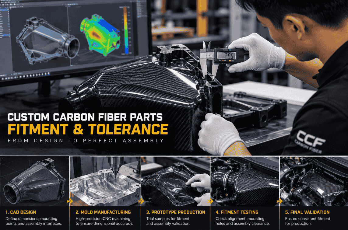
- Freeze the design revision. Confirm the STEP model, drawings, materials, mating components, and critical features all refer to the same revision.
- Complete DFM and assembly review. Identify undercuts, mold splits, joining methods, thickness assumptions, service access, and likely sources of variation.
- Agree on inspection criteria. Define datums, critical dimensions, visual standards, and how pass/fail decisions will be made.
- Manufacture the first prototype. Record the process and any deviations from the approved design.
- Measure critical features. Use suitable gauges, templates, coordinate measurement, or scanning as required; avoid treating a scan alone as proof of functional fit.
- Trial-assemble all mating components. Check fastener alignment, gasket compression, interference, access, and required clearances.
- Test on the intended vehicle or representative fixture. Validate real installation conditions, including nearby OEM and aftermarket parts.
- Document issues and corrective actions. Distinguish design changes from tooling corrections and process adjustments.
- Approve the production reference. Only after agreed validation should the sample become the reference for repeat manufacturing.
For parts exposed to heat, vibration, pressure, or repeated removal, a successful static fit check may be insufficient. Functional testing requirements should be defined by the responsible engineering team. Fitment validation does not, by itself, establish performance, durability, or safety.
7. Engineering Example: A Multi-Piece Carbon Fiber Airbox
Consider a custom automotive airbox consisting of a main housing, a removable filter cover, an intake duct, and several mounting brackets. Each piece may be manufactured separately, but the design must be validated as a complete assembly.
| Potential problem | Why it happens | Recommended prevention |
|---|---|---|
| Cover will not close | Flange geometry or laminate buildup creates interference | Review mating surfaces and inspect assembled prototype |
| Fasteners do not align | Hole positions reference inconsistent datums | Use a common assembly datum strategy |
| Air leaks at the lid | Uneven flange or uncontrolled gasket compression | Specify sealing requirements and perform relevant leak testing |
| Duct interferes with engine-bay hardware | Insufficient surrounding geometry or clearance study | Validate installation envelope on the target vehicle |
| Parts fit once but vary between batches | Uncontrolled layup, trimming, or fixture references | Document process and repeat inspection checkpoints |
In this situation, a phased manufacturing plan can still be sensible: prototype the interfaces that present the greatest uncertainty first, then validate the remaining components. However, phased production should not mean fragmented engineering. The entire system’s interface requirements need to be established before individual molds are finalized.
This is an illustrative engineering scenario, not a claim about a completed CCF project or validated product.
8. What Buyers Should Include in a Carbon Fiber Fitment RFQ
Better project information leads to a more meaningful manufacturing discussion. A useful request for quotation should include:
- 3D files: STEP/STP models for each part and the overall assembly, with revision numbers.
- 2D drawings: Critical dimensions, datums, tolerances, and special notes.
- Vehicle details: Make, model, year, trim, and any relevant modifications.
- Mating references: OEM parts, brackets, seals, fasteners, or verified scans.
- Material and finish: Laminate requirements, cosmetic surface expectations, and environmental conditions.
- Functional criteria: Sealing, temperature, vibration, access, and service requirements, where applicable.
- Acceptance criteria: Inspection method, sample approval process, and fit-test responsibility.
- Commercial context: Prototype quantity, expected production volume, and desired schedule.
- Which dimensions are achievable as molded, and which require secondary machining?
- What reference geometry is needed to assess fitment?
- How will the first sample be inspected and approved?
- Who is responsible for installation and functional testing?
- How are tooling revisions and design changes handled?
9. Common Mistakes That Increase Fitment Risk
- Sending only a cosmetic 3D surface without mounting and mating information.
- Assuming a STEP model contains every required tolerance and manufacturing instruction.
- Designing each component independently, then checking assembly only at the end.
- Applying unnecessarily tight tolerances to every surface, raising cost without improving function.
- Approving a prototype based only on photographs rather than measurement and trial installation.
- Changing the CAD revision after tooling begins without documenting the effect on interfaces.
- Assuming one vehicle test covers all variants and production batches.
Frequently Asked Questions
Can carbon fiber parts be manufactured to precise tolerances?
Yes, critical features can be controlled, but achievable tolerances vary with geometry, size, tooling, laminate design, process, and secondary operations. Agree on feature-specific requirements with the manufacturer instead of assuming a universal tolerance.
Does a STEP file guarantee that the finished part will fit?
No. A STEP file provides geometry, but fitment also depends on manufacturing allowances, datums, mating parts, tolerances, and validation. Dimensioned drawings and assembly information are often needed.
Should mounting holes be molded or drilled after curing?
Either approach may be appropriate depending on the design. Secondary drilling or machining can help control critical locations, provided suitable fixtures and damage-prevention methods are used.
Why does a carbon fiber lid not fit its housing?
Possible causes include incompatible flange geometry, thickness buildup, distortion, inaccurate trim, misaligned inserts, or unaccounted-for gasket dimensions. Inspect both components using shared assembly references.
Is 3D scanning enough to validate a prototype?
Scanning can help compare surfaces with CAD geometry, but it does not replace checking fasteners, seals, service access, operating clearances, and real installation conditions.
Can a complex assembly be manufactured in phases?
Yes, provided the complete system’s interfaces are defined first and each phase uses controlled design revisions. A phased plan can reduce risk, but final assembly validation remains essential.
Who should approve fitment before mass production?
The buyer and manufacturer should agree in advance on responsibilities. Typically, the designated engineering or product owner approves the prototype against defined inspection and installation criteria before production release.
Conclusion: Design the Assembly, Not Just the Individual Part
Reliable carbon fiber fitment begins before the first mold is made. It depends on accurate reference geometry, a realistic tolerance plan, well-defined mating interfaces, controlled manufacturing, and physical validation. For multi-piece systems, evaluating the complete assembly is especially important: every part can appear acceptable in isolation while the final product still fails to install or function correctly.
For OEM and aftermarket buyers, the most productive first step is to prepare a complete technical package and agree with the supplier on what must be inspected, tested, and approved.
Discuss Your Custom Carbon Fiber Project with CCF
Developing an automotive carbon fiber component or multi-part assembly? Share your STEP files, vehicle details, key interface requirements, and estimated quantities with CCF to discuss manufacturing feasibility and the next steps for your project.
Explore Wholesale & Custom ManufacturingRelated Resources
Continue exploring carbon fiber manufacturing requirements and automotive product applications:
Technical guidance is general and should not replace project-specific engineering review, validation, or applicable vehicle safety requirements.