Specify mounting inserts by describing the complete interface: mating part, position, access, operating conditions and required function. Naming a thread alone does not define a reliable mounting system. The responsible engineer must review the insert together with the surrounding composite and the proposed assembly.
For a custom carbon project, this information belongs at the beginning of development. Discovering tool access or bracket interference after a sample is made can create avoidable redesign and delay.
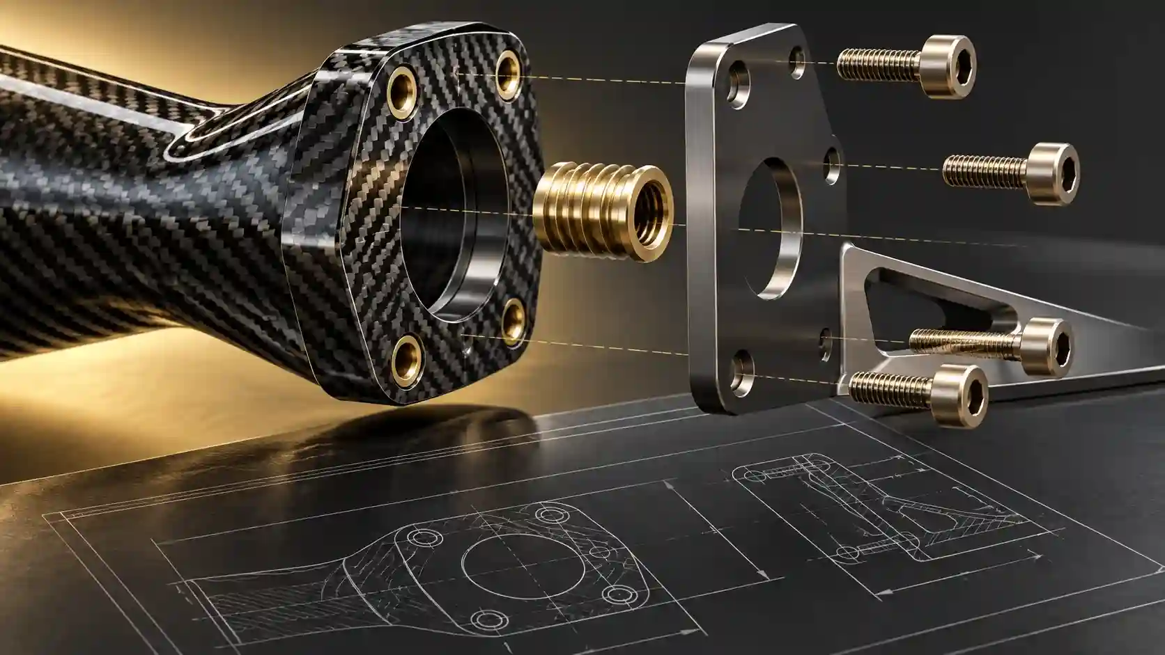
Start with the mating assembly
Provide the bracket, fastener and adjacent component information available for the project. Identify which elements are fixed by the vehicle and which may be redesigned. A clear photograph can explain access, while the engineering drawing or agreed geometry defines the actual interface.
State whether the connection locates a cosmetic component, supports a serviceable assembly or performs another specified function. Do not infer the engineering requirement from a marketing description such as “heavy duty.”
Build an interface input table
| Input | What the buyer should provide |
|---|---|
| Position | Agreed references or datums and identified mounting locations |
| Mating components | Relevant drawings, samples or verified geometry |
| Fastener requirement | Known thread and assembly constraints, where already specified |
| Access | Tool approach, surrounding clearance and service sequence |
| Use conditions | Relevant loads, vibration, temperature and exposure inputs |
| Service needs | Whether removal and refitting are expected |
| Verification | What evidence the engineering team must produce |
Mark unknown fields as unknown. An explicit gap allows the team to assign an investigation; a guessed number can become an unintended design requirement.
Leave design decisions to the responsible engineer
Insert type, surrounding laminate, bonding or retention method and assembly procedure need to be considered together. This article does not prescribe an insert design, torque or load rating. Those values must come from the approved project specification and relevant validation.
Do not assume an insert that fits the available space is suitable for the duty. Equally, choosing a larger thread does not automatically solve the complete interface problem. Ask the engineer to explain the proposed solution and what verification it requires.
If the insert interfaces with existing hardware, identify the actual parts rather than relying on a memory of their size. Where dissimilar materials or environmental exposure are relevant, ask the engineering team to review the complete interface and protection requirements.
Review assembly access before approving the layout
Confirm how the technician reaches the fastener, positions the mating part and follows the intended assembly sequence. A mounting point can be visible in a CAD view yet inaccessible in the installed vehicle.
Use a project-appropriate mock-up or review to resolve access questions before finalizing the layout. Record any vehicle components that must be removed and whether that work is acceptable for the intended installation. Do not hide an impractical service requirement in the final instruction sheet.
Control changes through the project
- Identify the interface drawing and revision.
- Record the agreed design inputs and unresolved questions.
- Review the proposed insert and assembly concept.
- Agree the verification and acceptance scope.
- Update related drawings and instructions when a change is approved.
A change in insert location or mating hardware may affect more than appearance. Notify the responsible team and review dependent parts before approving a revised sample. Keep old and new revisions identifiable so purchasing does not mix them.
For the quotation, separate development work, sample requirements and production assumptions. A price based on an unresolved interface should not be treated as a promise that every later design change is included.
An interface question with a clear engineering handover
Use this record as a buyer working tool. Examples and sample labels below are illustrative, not CCF inspection, order or test records.
| Record | Example or required entry |
|---|---|
| Buyer supplies | Mating bracket identity, mounting layout, access photographs and intended function. |
| Engineer resolves | Suitable design concept, required further inputs and project-specific verification. |
| Approval record | Drawing revision, responsible reviewer and applicable assembly instructions. |
Do not place guessed torque or load values into an empty field. A visible unknown is actionable; an invented input can silently become a design requirement.
For the connected decisions, use How to Plan a Test-Fit Vehicle Session for a Custom Carbon Fiber Project and How to Specify Heat-Exposure Requirements for Custom Carbon Fiber Trim.
Buyer FAQ
Is specifying the thread size enough?
No. Location, retention, surrounding construction, mating hardware and use conditions also need review.
Can I use a generic tightening value?
Use the approved assembly specification. A general fastener table does not establish a suitable value for an unvalidated composite interface.
What should I send for an initial review?
Provide the mounting layout, mating-part information, access photographs and intended function. Ask which additional inputs the engineering team needs.
Submit the Complete Mounting Interface
Send the layout, mating-part information, access views and intended function. Request an engineering review of the missing inputs and proposed scope.
Send an Inquiry
Include this article title, your product reference, vehicle details and the question you need resolved.