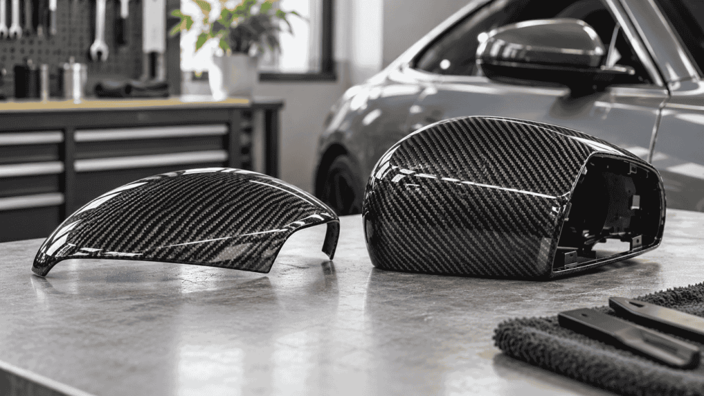
A custom carbon fiber part may look ready for production once the CAD model is complete. But who confirms that it is strong enough, fits the vehicle, survives its operating environment, and can be manufactured consistently? For OEM buyers and product developers, the answer depends on the agreed project scope—not simply on who supplies the STEP file or produces the mold.
This guide explains how buyers, design engineers, test partners, and composite manufacturers can allocate responsibilities before tooling begins. It also provides a practical responsibility matrix and an RFQ checklist for automotive carbon fiber development projects.
1. Three Common Custom Manufacturing Collaboration Models
Build-to-print manufacturing
The buyer supplies a controlled design package: 3D geometry, 2D drawings, material and process requirements, critical dimensions, and acceptance criteria. The manufacturer evaluates manufacturability, proposes process-related changes, produces the agreed components, and documents the inspections included in the contract. The buyer generally retains design authority unless the parties agree otherwise.
Collaborative engineering and manufacturing
The buyer and manufacturer jointly resolve geometry, laminate details, tooling strategy, interfaces, and production constraints. This arrangement can reduce iteration when roles are explicit, but creates ambiguity when design approval and validation ownership are left undocumented.
Turnkey product development
A single provider may be contracted to perform design, engineering analysis, prototyping, testing, and manufacturing. This broader scope must be expressly confirmed. A supplier’s ability to mold a part does not by itself mean it offers structural engineering, laboratory testing, or product certification.
2. Who Is Responsible for What?
The following is a sample allocation for discussion, not a universal industry rule. Replace each role with a named organization and accountable individual before issuing a purchase order.
| Activity | Typical lead | Evidence or deliverable |
|---|---|---|
| Define intended use, load cases and vehicle compatibility | Buyer / product owner | Requirements specification |
| Approve functional design and interfaces | Design authority | Approved CAD revision and drawings |
| Assess moldability and manufacturing access | Manufacturer | DFM comments and agreed changes |
| Specify laminate performance and material requirements | Design authority, with specialist input | Material / laminate specification |
| Plan and perform structural or thermal validation | Assigned engineering / test partner | Test plan and report |
| Build tools and prototype parts | Manufacturer | Tool and sample records |
| Inspect dimensions and appearance | Manufacturer or agreed inspector | Inspection results against criteria |
| Conduct installation and functional vehicle tests | Assigned buyer / test team | Fitment and performance report |
| Authorize design changes and production release | Named approver / design authority | Signed revision and release decision |
One organization may own multiple tasks. The important point is to specify who performs the work, who approves it, and who pays for additional work if the requirements change.
3. Does a STEP File Mean the Design Is Ready?
No. A STEP/STP file primarily transfers product geometry and, depending on the file and workflow, some associated product data. It does not automatically establish that the part will tolerate operating loads, engine-bay temperatures, vibration, fluid exposure, repeated fastener cycles, or the intended manufacturing process.
A supplier reviewing CAD should also request the applicable revision, drawing units, critical interface dimensions, fastening locations, surface requirements, intended installation conditions, and the definition of acceptable deviations. For complex assemblies, the full mating assembly or reliable interface geometry is often more useful than an isolated component model.
For more detail, read our guide to manufacturing carbon fiber parts from STEP files and the CAD files and measurement requirements checklist (confirm the latter article URL before publishing).
4. DFM Review Is Not the Same as Engineering Validation
Design for manufacturability (DFM) examines whether a proposed component can be made reliably with a selected process. Composite DFM can cover draft and release strategy, mold parting, undercuts, ply access, corner radii, laminate buildup, resin flow where applicable, trimming access, and dimensional repeatability.
Engineering validation asks whether the component performs its intended function safely and consistently. Depending on the application, this may require structural analysis, material coupon tests, thermal exposure tests, vibration assessment, fatigue evaluation, installation trials, or other evidence.
Define critical characteristics before tooling
Identify features whose failure would compromise function: sealing flanges, mounting holes, clip positions, interfaces to OEM parts, clearance to moving or hot components, and any safety-relevant surfaces. Record how each characteristic will be measured and what acceptance threshold applies. Do not assume a single general tolerance covers every feature.
5. What Testing Is Needed for Custom Carbon Fiber Parts?
The test program should follow the part’s function, risk, material system, and actual use conditions. Decorative trim and a structural or high-temperature engine component should not share an identical validation plan.
| Verification type | What it answers | Possible evidence |
|---|---|---|
| Dimensional inspection | Does the produced part match approved geometry? | Caliper, fixture, CMM or scan records as appropriate |
| Visual and surface inspection | Does it meet the agreed cosmetic criteria? | Approved sample, defect criteria, photos |
| Assembly / fitment testing | Do the parts install and mate without interference? | Trial assembly and installation checklist |
| Material / laminate verification | Are specified materials and laminate characteristics met? | Material traceability, process records, relevant tests |
| Thermal / environmental assessment | Will the part withstand anticipated conditions? | Exposure protocol and results |
| Structural / vibration / fatigue testing | Can it withstand relevant service loads? | Analysis or physical test reports |
| Functional vehicle validation | Does the installed system perform as intended? | Vehicle-level test plan and findings |
Tests should specify the specimen, operating condition, method, pass/fail criteria, responsible party, and who signs off. An attractive prototype photograph or a successful bench fitment check is not proof of durability or performance.
6. Example: A Multi-Part Carbon Fiber Intake Enclosure
Consider a custom intake project comprising an airbox, removable filter lid, connecting duct, and engine-bay cover. These pieces may be manufactured in separate phases, but their interface geometry should be coordinated as one system.
- System definition: The buyer defines vehicle packaging, mounting points, service access, operating temperatures, filtration requirements, and performance objectives.
- Design authority: A named engineering team controls mating geometry, seal compression, fastener strategy, and interface revisions.
- Manufacturing review: The supplier assesses mold release, laminate access, trim lines, flange stability, and feasible tooling approaches.
- Prototype inspection: Each part is checked against approved dimensions, then assembled with mating parts and relevant vehicle interfaces.
- Functional verification: The designated test party evaluates sealing, clearance, thermal exposure, vibration, and airflow or other performance criteria as required.
- Production release: The buyer and supplier approve a controlled design revision and inspection plan before repeat orders.
Manufacturing one cover successfully does not validate the complete intake system. Equally, a prototype that installs correctly may still need environmental and functional evaluation.
7. What Happens When a Design Changes or a Test Fails?
Without change control, it is easy for a manufacturer to produce to an outdated CAD revision while the buyer assumes the latest version is in use. Use a written engineering change request that records the reason for the change, affected parts, revision numbers, impact on tooling and schedule, and approval status.
Separate root cause from commercial responsibility
If a prototype fails fitment or testing, determine whether the cause is an incomplete requirement, a design error, a tooling deviation, a manufacturing defect, an assembly issue, or an unrealistic test condition. Responsibility for rework or retesting should follow the agreed contract and the documented cause—not an automatic assumption that either party is always at fault.
Set approval gates
Useful project gates include requirements approval, DFM acceptance, design freeze, tooling release, first-article review, functional validation, and production approval. A gate should identify the evidence needed and the person authorized to approve it.
8. Buyer Checklist Before Requesting a Quote
- Vehicle make, model, year, variant, and intended installation location.
- Current CAD/STEP revision, 2D drawings, interface dimensions, and reference photos.
- Part function, expected loads, thermal exposure, and environmental conditions.
- Required material, finish, appearance standard, and critical tolerances.
- Which party owns the design, DFM decisions, test plans, and final approval.
- Expected prototype quantity, target order volume, and development milestones.
- Required inspection reports, samples, tests, and acceptance criteria.
- Tooling ownership, storage, revision rights, confidentiality, and change-cost terms.
For early-stage projects, label unknown values explicitly instead of inventing precise specifications. Ask potential suppliers which missing inputs prevent a reliable feasibility review or quotation.
9. Frequently Asked Questions
Does a carbon fiber manufacturer automatically provide engineering design services?
No. Manufacturing, CAD support, engineering analysis, and product testing are distinct services. Confirm the exact scope and deliverables with each supplier.
If I provide a STEP file, who is responsible for design errors?
That depends on the contract, the approved design authority, and the nature of the error. A manufacturing review does not automatically transfer responsibility for product performance.
Is prototype fitment enough to approve mass production?
Not necessarily. Fitment verifies installation and interfaces under the tested conditions. Other material, durability, environmental, and functional requirements may still need validation.
Who should pay for testing?
Agree on test scope, provider, sample quantities, costs, and retest terms before starting. There is no single arrangement that applies to every OEM project.
Can testing be performed by an independent laboratory?
Yes, when appropriate. The buyer and supplier should agree on the laboratory’s capabilities, methods, specimen requirements, and acceptance criteria.
What is a design freeze?
A design freeze is an agreed baseline revision used to release tooling or production work. Later changes should follow documented review and approval.
What is the difference between first-article inspection and product validation?
First-article inspection generally checks initial production output against specified requirements. Product validation assesses whether the design meets its intended functional and operating requirements; both may be needed.
Discuss Your Custom Carbon Fiber Project
Have CAD drawings, a prototype concept, or an OEM development brief? Share your vehicle details, drawings, target quantities, and known validation requirements with CCF to discuss manufacturing feasibility and the appropriate next steps. Available engineering and testing services should be confirmed for each project.
Contact CCF About Wholesale & Custom ProjectsRelated Guides
Editorial note: This article provides general project-planning guidance. Actual engineering, validation, and manufacturing responsibilities depend on project scope, contract terms, application, and applicable requirements. Confirm the related-article URLs before publication.